Marine Induction Motor Servicing Tips
Tips for Servicing Marine & Land Based Induction Motors.
These tips for marine induction motor servicing, are for education only, and should not be relied on as instructions.
Smart Manufacturing technologies can be applied to Induction Motors, to reduce servicing down time.
Wirelessly connected sensors can be used to monitor Induction motor parameters.
Such parameters include bearing vibration increases, and current in the Stator coils.
Only competent trained electrical personal should attempt to service marine induction motors.

Tools Required
Safety & Isolation of supply of induction motors.
Taking a casual approach to electricity can prove fatal.
This is especially true when we are talking about three-phase motors, as they operate in the UK & EU at 400 Volts Alternating Current (400 VAC).
Marine installations typically operate at an even higher 440 Volt Alternating Current (440 VAC).
Never work on a piece of three-phase machinery, such as an induction motor unless you are both qualified to do so, and have authorisation.
People able to give authorisation include senior managers, with appropriate responsibilities, in the case of onshore factory installations.
For work to be carried out aboard Ships, permission from someone such as the Chief Engineer is appropriate.
Once permission has been gained, and the appropriate paperwork issued, only then can work commence.
Certainly in the marine environment, and normally onshore as well, ‘locks and tags’ will be issued.
The lock is to ensure that once an isolator switch has been turned off, no one can switch it back on accidentally.
The ‘tag’ details who has isolated the supply, and is working on that circuit.
Only the person who has been issued with the lock and tag set, can remove them.
Double check that circuit is dead.
Another marine induction motor servicing tip is don’t assume that just because you have locked and tagged the appropriate electrical isolator, that you are safe to work on a circuit.
The isolator may be incorrectly labeled, or even worse, you have taken someone else’s word for it.
Before you stick your fingers in, and potentially kill yourself, you need to use an appropriate device to check that the circuit is safe to work on.

Induction Motor
There are three possible devices that can be used:
- Test Bulb
- Multimeter / Voltmeter
- Line Tester
Firstly lets look at the test bulb as an option.
A test bulb with appropriate leads and clips attached, can provide indication of a live circuit, but has a flaw.
If the bulb filament breaks, then you could falsely assume that the circuit is safe to work on, with possibly fatal outcomes.
The second option is the Multimeter / Voltmeter which these days will probably be a ‘solid state’ digital type, rather than the older analogue types, which are commonly referred to as ‘AVO’s’ in the UK.
The Multimeter / Voltmeter being ‘solid state’ is more likely to be a bit more reliable than, a filament bulb tester. However it still may be broken, and you would not necessarily know. An example being the test probe wires may be ‘Open Circuit’.
The third option, the ‘Line Tester’, will provide the most reliable indication of whether a circuit is safe. Therefore this is the preferred option.
The reason that a line tester is safer is because it contains four separate Neon bulbs (some modern ones are LED).
The bulbs light up according to how high the voltage is, for example a 400 VAC supply would light not only the 400VAC light, but the lower voltage indicator lights as well.
So imagine that the 400VAC indicator bulb has broken.
The lower voltage indicator bulbs will still light up, for example the 230VAC and 110VAC indicator bulbs.
Therefore the engineer will still have an indication that there is voltage in the circuit, and can investigate further.
Before using a Line Tester you should use a ‘proving unit’. A proving unit is a small hand-held device capable of producing a voltage such as 250 Volts.
The Line tester can thus be tested using the proving unit, prior to testing a real live circuit.
To test the Line Tester the two probes are pushed against the Proving Unit which then produces a voltage.
This will be indicated by an indicator LED lighting up on the proving unit itself.
The Neon or Led indicator lamps of the Line Tester should also light up at the same time, to indicate the voltage being supplied.
Tips when changing bearings on Induction Motors
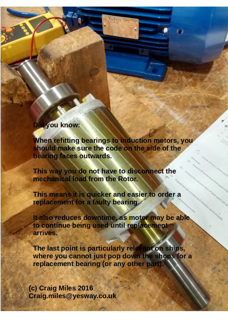
Importance of identification code facing outwards.
When refitting bearings to an induction motor you will notice that the bearing itself has a code written on the one side of it.
This code is the product identification code, and is what you need to quote in order to order the correct replacement bearing.
Once the correct replacement bearing has been obtained, and is ready for fitting, ensure the following.
Firstly, that the bearing identification code is facing away from the Stator, and outwards towards the end of the motor shaft.
This will help you in the future, if you ever have to replace the bearings again.
The reason for this is that you can just remove the end plate of the induction motor, and read the bearing code easily, provided it has been fitted with the code facing outwards.
If the bearing code was facing inwards, then it is harder to read the bearing code, and might mean that the motor shaft has to be disconnected from its mechanical load.
This adds to the motor downtime, and hence has financial and productivity implications.
Ways to remove bearings from induction motor shaft.
The ideal way to remove an old bearing from the induction motor rotor shaft is to use a bearing puller tool.
Removal is then just a matter of fitting, the tool into position, and winding in the screw thread in a clockwise direction.
As this happens, the bearing is slowly pulled up and off the shaft.
If however you don’t have a puller, other methods, such as using a metal bar to leverage between the bearing and the end of the shaft can be tried.
However this is not the way I recommend, and you do it at you own risk of injury and damage to the motor shaft.
Methods for fitting a new induction motor bearing when marine induction motor servicing.
Ideally you will have a hydraulic bench press, that you can use to put massive pressure down onto the bearing to ‘press it’ onto the shaft, in the correct position.
When using such a press, a number of precautions should be observed.
Firstly, ensure that you are fully competent to use the hydraulic press. Even fairly cheap versions are capable of exerting many tons of pressure, which can be dangerous to human health.
Secondly, ensure that the tube or sleeve that you fit over the shaft of the motor is only just wide enough.
The reason for this is that a wide metal tube (or sleeve) put over the motor shaft in order to push against the bearing, can damage it.
This is because too wide a tube will make contact with the plastic middle of the bearing, or the outer metal edge.
Both of these two scenarios are bad, because pressure applied to anywhere but the centre metal part of the bearing, will cause damage.
This damage can result in the replacement bearing being ruined, which defeats the object of replacing it.
Using a hydraulic press is the method that we would recommend, however this option is sometimes not available.
In particular to engineers working at sea in a marine environment, such as a cargo ship.
If you find yourself in this situation, then there are other ways to re-fit a replacement bearing to an induction motor.
One method is to take advantage of the fact that metals contract and expand due to cold and heat.
This method involves carefully wrapping up the Stator part of the induction motor in a polythene bag, and putting it in the freezer overnight.
This will very slightly shrink the size diameter of the bearing shaft.
The second part to the operation involves gently heating up a pan of engine oil, so that it is warm.
Obviously extreme care needs to be taken, so that either a fire is not caused by the oil igniting, or the engineer receiving burns while trying to handle the hot bearing.
Once the bearing is warm, the Stator can be removed from the freezer, and the warm oiled bearing should slip fairly easily onto the shaft.
The oil can then be wiped off the bearing with a non fluffy cloth, and motor reassembly can begin.
For more tips on marine induction motor servicing, why not check out the authors (and our founders) personal website at www.craigmiles.co.uk/blog