Transformers – Single Phase Type
Transformers
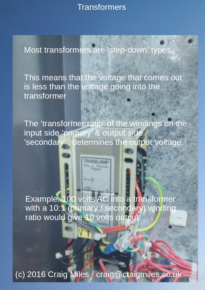
Transformers are most commonly ‘step-down’ types.
This means that the voltage that comes out is less than the voltage going into the transformer.
The ‘transformer ratio’ of the winding’s on the input side ‘primary’ & output side ‘secondary’, determines the output voltage.
Example: 100 volts AC going in with a 10:1 (Primary / Secondary) winding ratio, would give 10 volts output.
-
Information about Single phase Transformers
There are two main types that you will come across.
Single Phase
&
Three Phase
The difference between the two types is that Single Phase have four electrical connections, whereas Three Phase have six.
In the case of a Single Phase Transformer, the four connections consist of two input connections, and two output connections.
The Three Phase types six connections, consist of three input connections, and three output connections.
Both single phase and three phase transformers will only work with Alternating Current (AC).
AC was invented by Nikola Tesla over 100 years ago, and is the dominant system used (as opposed to Direct Current (DC), for electricity transmission.
AC is the electricity that comes out of a wall socket in a house, in nearly all installations around the world.
Unlike Direct Current (DC) in which the polarity of the two connections stays constant (has a fixed + & -), AC voltage ‘Alternates’.
The ‘Alternating’ in Alternating Current (AC) means that the voltage in the two wires is constantly changing direction and level.
The picture below shows what is actually happening

The picture above shows an AC Sine Wave.
As you can see, the ‘wiggly’ line travels both above and below the straight horizontal line.
The horizontal line represents the 0 Volts level, and below the line is minus volts, and above plus volts.
The two wires of a single phase transformer are connected in a fixed position, but the picture shows what is happening in each of the wires.
The peaks represent the peak voltage in one of the two wires, therefore if the voltage is at the peak in one wire, it is the opposite level in the other wire.
The ‘alternation’ of the voltages in the two wires happens rapidly and constantly.
The speed of change is called the Frequency, and is measured in Hertz (Hz)*.
*It is worth noting that on older pieces of British machinery such as Transformers and Induction Motors, you may find Frequency described as ‘Cycles’, rather than Hz.
In the UK and Mainland Europe the frequency of the mains electricity supply is 50Hz, whereas in countries like the USA and Japan, it is 60Hz.
This constant frequency of voltage change creates electromagnetic induction in the transformer.
Transformers rely on electromagnetic induction for their operation.